
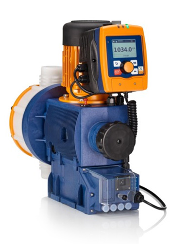
A metering pump can run perfectly in local mode and still fail as part of an automated process. The usual reason is not pump capacity; it is an incomplete interface. The PLC sends a command but has no run proof. The analog scale differs at each end. A no-flow alarm trips during normal priming. The pump stops on low tank level, yet the control room sees only “not running”. Good integration defines commands, permissives, feedback, units, timing, and failure behaviour before wiring begins.
At Jams (Pvt.) Ltd, we build the signal list around the dosing process and the selected motor-driven metering pump. The exact interface varies with pump controller, option package, PLC platform, and process risk. This guide explains the engineering questions that apply whether the plant uses Siemens SIMATIC, Allen-Bradley Logix, or another industrial controller.
Choose the control mode first
The PLC should not send several competing references. State which mode owns the pump:
- Local manual: maintenance or commissioning runs the pump from its own controls, with remote commands blocked and status visible.
- Remote fixed rate: the PLC enables a preset pump rate stored locally or in the controller.
- Analog proportional: a 4-20 mA reference represents the commanded stroke frequency, speed, capacity, or dose.
- Pulse paced: incoming pulses from a water meter or PLC command discrete dosing increments according to a declared ratio.
- Digital communication: a supported fieldbus carries commands, values, status, diagnostics, and parameters.
- Closed-loop process control: the PLC adjusts dose from flow plus a measured quality variable within approved limits.
Define how mode changes occur, whether the pump may change while running, and what output is used during transition. Local operation must not create an unnoticed chemical feed when the main process is stopped.
Minimum command and status set
A basic interface often needs more than start/stop. Review the following signals against the pump’s actual terminals and options:
- Remote enable or start command.
- Rate reference and reference-valid indication.
- Local/remote or manual/automatic status.
- Running or stroke activity feedback.
- Common fault plus available specific diagnostics.
- Low chemical level and low-low trip from the tank system.
- Leak detection, diaphragm alarm, or liquid-end monitoring where fitted.
- Flow confirmation or no-flow alarm from an independent monitor where required.
- Actual rate, stroke frequency, total strokes, or delivered-flow value if supported and meaningful.
Do not infer chemical delivery from “motor running”. A blocked suction, air lock, empty tank, closed valve, failed check valve, or loss of prime can leave the drive operating without the intended dose. Where dosing consequence justifies it, add independent flow or process confirmation.
Scale analog signals unambiguously
For 4-20 mA control, write the equation in the functional specification. For example, 4 mA may equal zero and 20 mA may equal the approved maximum rate—not necessarily the pump’s nameplate maximum. State whether the reference represents litres per hour, percent capacity, strokes per minute, or motor speed. Use the same range on the pump, PLC, HMI, historian, and commissioning sheet.
Define underrange and overrange behaviour. A signal below the valid threshold may indicate a broken wire rather than a low command. Decide whether the pump stops, holds a safe fallback, or alarms and continues. The answer depends on the chemical and process hazard; it should not be left at a default parameter.
Engineer pulse pacing as a quantity relationship
Pulse control is common when dose follows a main water meter. The design must state input pulse weight, desired chemical dose, solution concentration, pump volume per stroke or command pulse, and maximum pulse frequency. At high process flow, the requested pulse rate must remain within the pump input and achievable capacity.
Also decide what happens during a pulse burst, communications interruption, or PLC restart. Buffered pulses can cause delayed overdosing if handled poorly. Where the source meter has a slow pulse resolution, a smooth analog or digitally calculated reference may provide better control. Confirm the calculation with units throughout:
- Process flow or volume in a declared unit.
- Target active-chemical or solution dose.
- Solution concentration and density where required.
- Required pump flow.
- Command pulse frequency or analog percentage.
Build permissives from process conditions
A start command should pass only when the dosing path is ready. Typical permissives include main process flow proven, chemical tank above low-low, suction and discharge valves in approved position, mixer running where required, injection point available, bund leak clear, pump healthy, and emergency or safety conditions reset. Not every project needs every signal; the hazard and operating philosophy decide.
Use a cause-and-effect matrix to show which condition inhibits start, which stops a running pump, which only alarms, and whether restart is automatic. A low-low tank may latch a stop until replenishment and inspection. A momentary loss of main-flow signal may use a short delay, but an extended loss should prevent dosing into a stagnant line.
Separate regulation from protection
A PLC PID loop may trim pump output from pH, chlorine residual, conductivity, or another analyser. Analyser dynamics are often slow because of mixing, transport, and sample delay. Tune conservatively, limit the trim, apply anti-windup, and keep a flow-proportional feed-forward component where appropriate. Otherwise the controller can chase old information and alternate between overdose and underdose.
Independent protection may still be needed. Maximum dose limits, high process concentration alarms, injection interlocks, relief arrangements, and chemical-specific safety functions should follow the process hazard review. A standard PLC calculation is not automatically a safety instrumented function.
Integrate Siemens or Allen-Bradley without changing the fundamentals
SIMATIC analog and digital I/O, distributed ET 200SP stations, or approved communications can implement the interface when selected and configured correctly. The JAMS Siemens authorisation information provides the principal context for local support. In a Logix architecture, Allen-Bradley controller and I/O families can perform the same process functions; see our Allen-Bradley authorisation section.
Platform-specific data types, scaling instructions, diagnostic tags, and network configuration differ, but the functional specification should remain vendor-neutral enough to state the required behaviour. Do not bury the process rules only inside ladder logic or a proprietary function block.
Commission from terminals to chemistry
- Confirm pump model, controller options, terminal assignments, voltage levels, isolation, and PLC channel type.
- Test every digital input and output with the process in a safe condition.
- Inject known analog values at 4, 12, and 20 mA and compare pump, PLC, and HMI interpretation.
- Verify pulse weight and maximum frequency using a controlled test.
- Prove local/remote transfer and the defined response to cable break, PLC stop, network loss, and power restoration.
- Test each permissive and trip, including the first-out indication and reset rule.
- Prime and calibrate the pump using an approved method and safe fluid where the procedure requires it.
- Run water or process commissioning under controlled conditions before enabling automatic chemical control.
- Record final pump parameters, PLC scaling, setpoints, alarm delays, and software backups.
A calibration column or drawdown test measures actual delivered volume under the test conditions. Backpressure, chemical properties, check-valve condition, and suction arrangement affect results. Enter a calibration factor only through an approved procedure and preserve the original and revised values.
Maintain the complete loop
Routine work should test more than the liquid end. Inspect signal wiring and connectors, compare commanded and displayed rate, prove low-level and no-flow alarms, review bypassed interlocks, and check whether operators have left pumps in local mode. Trend recurring faults to distinguish instrument problems from suction or discharge issues.
Prepare an integration enquiry
Send the chemical, concentration, required flow and pressure, pump model or proposed duty, main-process measurement, control philosophy, PLC platform, available I/O, preferred interface, power supply, hazardous-area status, and alarm requirements. JAMS can then review the pump and controls as one scope. Use our contact page to share drawings and the draft signal list.
Frequently asked questions
Is a run contact enough to prove dosing?
No. It proves only the state represented by that contact, often drive or stroke activity. Actual chemical delivery may require an independent flow monitor, calibration, tank mass balance, or process measurement depending on risk and accuracy requirements.
Should the PLC command percent or litres per hour?
Either can work if the mapping is explicit. Engineering units are clearer to operations, while the pump may accept percent or frequency internally. Document conversion, maximum approved rate, calibration factor, and limits at every layer.
What should happen when the 4-20 mA cable breaks?
Detect the invalid signal and apply the approved fail response—often stop and alarm, but some processes require a defined fallback. The hazard review and control narrative must decide; do not rely on an undocumented device default.
Can pump control be handled entirely over a digital network?
It may be possible with supported options, but assess network availability, update time, diagnostics, cybersecurity, and behaviour on communication loss. Some critical permissives or stops may remain hardwired according to the project risk assessment and site standard.