Choosing an industrial flow meter begins with the measurement purpose, not the process-connection size. The same pipe may need a meter for energy accounting, process control, leak detection, custody-related reporting or temporary troubleshooting. Those purposes demand different ranges, evidence, outputs and installation quality. A technically attractive sensor can still be the wrong investment if it cannot answer the plant’s actual question.
Jams (Pvt.) Ltd uses a structured checklist to help Pakistani plants compare measuring principles and configurations. The checklist does not replace manufacturer selection data or application review; it makes sure the right information reaches that review.
1. Define the decision and measurement boundary
Write one sentence describing what will change because the meter exists. “Measure utilities” is vague. “Trend compressed-air consumption of Line 2 by shift and alarm on off-production demand” defines a boundary, time scale and user. For a steam meter, the purpose might be boiler-house balance; for water, it may be batch control; for gas, departmental allocation.
Identify whether the meter is permanent, portable or part of a campaign. State who will read it, where data will go and how often it must be reviewed. This prevents buying advanced communication features that the site will not integrate—or a local-only display when historical evidence is essential.
2. Describe the medium completely
Name the gas, liquid or steam and include composition where it can vary. Record normal and maximum pressure and temperature, moisture state, contamination, particles, oil carryover, conductivity where relevant and any corrosive or hazardous properties. For mixed gases, provide the expected composition range because some principles depend strongly on fluid properties.
Do not use “air” to describe every gas service or “water” for every liquid. Instrument air, wet compressed air and aeration air present different conditions. Treated water, brine and chemical solution can differ materially in compatibility and sensing behaviour.
3. Build a real flow envelope
Provide minimum, normal and maximum flow with units and reference conditions. Add expected start-up peaks, reverse flow, zero-flow periods and rate of change. If values are estimated from compressor capacity or pump rating, label them as estimates. Oversizing a meter for an unlikely maximum can sacrifice useful resolution at normal operation.
For gas flow reported in standard or normal volume, define base pressure and temperature and whether values are absolute or gauge where applicable. Align these conventions in the sensor, display, PLC and reporting system.
4. Match the measuring principle to the duty
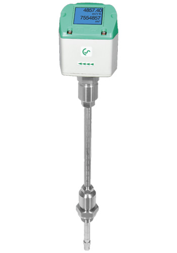
Thermal mass and vortex technologies illustrate why there is no universal meter. The VA 500 can be considered for compressed air and suitable gases where its thermal mass principle, configuration and installation conditions fit the application. It can support standardized flow measurement without a separate external compensation arrangement of the type required by some volumetric methods. Gas composition and contamination still matter.
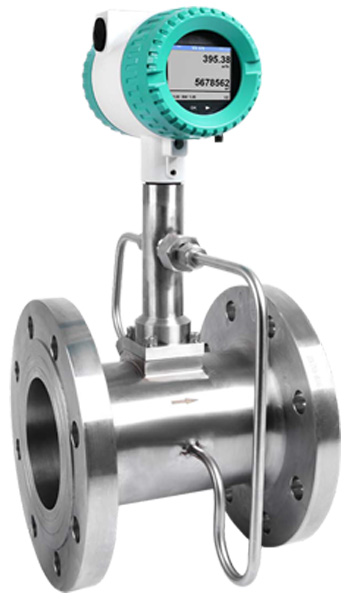
The VX 570 vortex sensor can be considered for appropriate steam, liquid and gas duties. Vortex measurement depends on a suitable flow regime and application-specific compensation or inputs where mass or standardized values are required. Low-flow performance, vibration, medium condition and installation geometry need attention.
Other principles may be more suitable for conductive liquids, dirty services, very low flow, bidirectional duty or applications with particular accuracy and pressure-loss needs. The checklist should lead to a principle; it should not force every application into the products already familiar to the plant.
5. Survey the pipe and installation location
Confirm pipe outside diameter, wall thickness or schedule, internal diameter, material, lining and orientation. Note nearby bends, valves, reducers, tees, filters and control devices. Measure available straight run instead of describing it as “enough.” Photograph the location from several angles and identify safe access for installation and future removal.
For insertion instruments, depth and orientation are part of the measurement geometry. Pressurized installation or retraction requires appropriate hardware, procedure and competent personnel. For inline meters, flange rating, face-to-face length, support and shutdown requirements affect project cost. Ambient temperature, weather, dust, washdown, vibration and area classification also belong in the selection.
6. Set performance requirements that serve the purpose
Accuracy statements must be read with their conditions and basis. Percentage of reading, percentage of full scale and combined terms behave differently across the range. Repeatability may matter more than absolute accuracy for a control loop, while an energy balance needs traceable and aligned measurements. Define the acceptable uncertainty at normal and minimum operating points.
Also consider response time, turndown, pressure loss and bidirectional capability. A fast display is not automatically a more accurate one, and excessive damping can hide short events while insufficient damping creates a noisy control signal.
7. Specify outputs, power and data ownership
List available power, analogue signal, pulse or frequency, digital communication protocol and cable distance. Define scaling, engineering units, update rate and fail-state behaviour. If a data logger or plant system is involved, agree timestamps, tag names, totalizer handling and data retention.
A totalizer that resets during power loss or a PLC conversion using different base conditions can undermine months of reporting. Commission the complete data chain from sensor to dashboard, not only the local display.
8. Plan maintenance and metrological checks
Ask how the sensor will be inspected, cleaned, removed and checked. Contamination, erosion, condensate, coating or physical damage affect technologies differently. Identify isolation and access needs and whether the plant can hold a spare. Calibration requirements should follow process risk and quality systems rather than a copied annual interval.
Commissioning establishes correct identity, installation, configuration and signal operation. Calibration is a separate comparison under defined conditions. State which documents are required with supply and what field verification is practical.
9. Compare lifecycle scope, not only meter price
Include process fittings, isolation hardware, cable, display, logger, communication gateway, installation labour, shutdown, commissioning, calibration, spares and maintenance access in the comparison. A lower-cost sensor that requires major pipe modification may not be the lower-cost measurement point. Conversely, avoid buying a complex system where a simple local indication genuinely answers the need.
JAMS supports application review through its measuring technology services. Send the completed checklist, photographs and operating data so we can discuss a technically appropriate route without assuming one model suits every medium.
Frequently asked questions
Can we select a flow meter from pipe size and maximum flow?
No. Those are important inputs, but medium, pressure, temperature, minimum flow, installation geometry, contamination, purpose, outputs and performance requirement can change the correct technology and configuration. A short application sheet prevents expensive assumptions.
What is the main difference between VA 500 and VX 570?
They use different measuring principles and target different application envelopes. VA 500 uses thermal mass technology for suitable compressed-air and gas duties. VX 570 uses vortex technology for suitable steam, liquids and gases. Final selection requires the exact medium and operating conditions.
How much straight pipe is required?
There is no single answer for all meters and disturbances. Requirements depend on the principle, model, upstream fitting and installation. Provide a piping sketch and actual dimensions, then follow the selected manufacturer’s instructions. A flow conditioner may help some applications but is not a universal cure.
Should a new meter always be integrated into the PLC?
Only when integration supports the decision and the plant can maintain the data chain. A temporary survey may need local logging; a control loop needs reliable real-time output; energy reporting may need a historian. Define ownership, units and failure handling before choosing the interface.