
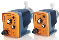
Compact solenoid metering pumps are practical where a utility point needs controlled chemical feed at relatively modest capacity. Typical examples include disinfection, pH correction, corrosion-inhibitor feed, small cooling circuits, boiler-support chemicals, and dosing into package water systems. Their compact footprint can make installation look simple, but repeatable performance still depends on correct capacity range, pressure, chemical compatibility, suction layout, injection accessories, and control logic.
The ProMinent BETA/X family belongs to this compact dosing category. Jams (Pvt.) Ltd supports ProMinent applications in Pakistan as an authorized partner, with details available in our ProMinent authorization section. The family should be selected from verified model data for each duty. A familiar name is not a substitute for checking the fluid, hydraulic system, environment, and signals at the intended utility point.
How solenoid metering differs from motor-driven duty
A solenoid metering pump uses an electromagnetic actuator to produce reciprocating strokes at the liquid end. During each cycle, the check valves direct a controlled displacement of chemical. Average flow depends on stroke characteristics and frequency. The discharge remains pulsating, even though the hourly dose can be stable.
Solenoid pumps suit lower capacities where compact arrangement and control options fit local utility dosing. Larger continuous flows or higher hydraulic demand may point toward a motor-driven pump. JAMS reviews both through its metering-pump service. The boundary follows actual model curves and process requirements, not a rule that one drive type is always superior.
- Define minimum, normal, and maximum chemical flow at operating pressure.
- Check whether the fluid releases gas, crystallises, contains solids, or has high viscosity.
- Confirm the available power and the required local or remote control method.
- Plan safe tank level monitoring, priming, pressure relief, and injection.
- Leave access for valve service, diaphragm work, calibration, and chemical cleanup.
Calculate the utility dose before selecting BETA/X
Convert the treatment target into product volume. For flow-proportional water treatment, use water flow, required dose, product active strength, prepared concentration, and density. For batch duty, use total product volume and the time allowed for injection. Evaluate low and high process conditions. If normal requirement lies at the extreme bottom of a much larger pump, selecting “extra capacity” can make control less useful.
Utility flows are often more variable than operators realise. A bore pump cycles, a softener regenerates, a cooling loop changes load, or a package plant runs only during a shift. A fixed pump setting then changes the chemical ratio. Pulse pacing from a water meter or an analogue signal from a flow transmitter can improve proportional feed when supported by the selected pump configuration and a properly scaled control design.
Establish realistic pressure conditions
Calculate pressure at the injection point plus static head, line friction, injection-valve opening pressure, and accessory loss. Check the pump’s capacity at that pressure. If the point enters an open tank or low-pressure line, guard against siphoning and unstable check-valve operation. Back-pressure and anti-siphon functions may be required even though the process itself is near atmospheric.
Positive-displacement discharge needs protection from a closed valve or blocked injection fitting. Select a compatible relief arrangement with a safe return destination. Never rely on flexible tubing swelling as pressure protection. Tubing, connectors, valves, calibration equipment, and the injection quill need pressure and chemical ratings suitable for the complete duty.
Pulsation is normal but must be accommodated
Each solenoid stroke sends a small pulse into the discharge. In many short utility lines this is acceptable. Long flexible routes, sensitive flow switches, small mixers, or rapid analyser response can reveal the pulses. Do not add a dampener automatically; first check pulse volume, line, pressure, and required process smoothing. If installed, it must be compatible, correctly charged where applicable, and coordinated with back-pressure devices.
Pay special attention to the chemical
Sodium hypochlorite is common in compact disinfection duties and can release gas as temperature and age increase. Gas in the liquid end prevents complete filling and causes apparent loss of capacity. Keep suction short, avoid unnecessary lift, manage storage temperature and solution age, and select a suitable configuration. Repeated manual priming is not a long-term strategy.
Acids and alkalis require exact concentration and temperature for materials review. Some products crystallise around valves. Viscous inhibitors may need larger suction lines. Suspended solids can prevent small check valves from seating. Review head, diaphragm, seals, balls, seats, tubing, foot valve, injection valve, and tank fittings as one wetted system.
Design the suction side for dependable filling
Mount the pump close to the day tank and preferably with favourable suction head when chemical safety permits. Avoid loops that trap gas. Use a line size and foot valve suitable for the model and fluid. Tank vents should remain open and safe; a sealed tank can create vacuum as chemical is withdrawn. Low-level shutdown prevents the pump from drawing air and provides time for replenishment.
A calibration column, where chemically appropriate, helps verify delivery. Its connection should not create an air leak during normal service, and operators need a clear valve sequence to avoid drawing the column empty or isolating the tank unexpectedly. Bunding and drain arrangements should keep spilled chemicals separated when incompatibility exists.
Choose control behaviour that operators understand
Local manual operation suits a genuinely fixed duty, but interlocks are still needed where dosing must stop with process flow. Pulse input can add a defined amount per water-meter pulse when rate and capacity are coordinated. Analogue pacing can map flow to pump demand. Document scaling and test the endpoints; wiring alone does not prove the dose ratio.
Define behaviour for power restoration, signal loss, low tank level, and pump fault. If an analyser trims the dose, limit its authority and account for sample delay. Stroke indication shows actuator activity, not necessarily liquid movement. Critical points may need flow monitoring, inventory reconciliation, or residual verification.
Keep the local installation serviceable
Compact pumps are sometimes squeezed behind tanks or beneath pipework. That makes valve cleaning, diaphragm maintenance, and safe disconnection difficult. Provide indication, secure tube routing, isolation, lighting, labels, and room for a service container. Electrical enclosures must suit washdown, dust, heat, and chemical vapour as applicable.
Commissioning and routine verification
Verify model, liquid-end materials, valve orientation, power, earthing, control inputs, tubing support, relief path, and chemical labelling. Prime by the manufacturer-approved method with suitable personal protection. Test interlocks before relying on them. Measure delivery at representative back pressure and record the pump setting, command, test duration, measured volume, solution concentration, and date.
Routine checks should include tank level, leakage, tubing condition, valve cleanliness, alarm history, and comparison of expected chemical consumption with inventory. A sudden change in consumption may indicate a process change, siphoning, incorrect solution preparation, or loss of pump delivery. Maintenance frequency should follow the chemical, duty cycle, site observations, and current manufacturer instructions.
Common compact-dosing pitfalls
- Choosing a model from maximum free-discharge capacity rather than flow at pressure.
- Oversizing so normal demand requires an impractically low setting.
- Using long narrow suction tubing for a gas-releasing or viscous chemical.
- Omitting anti-siphon protection on a low injection point.
- Assuming stroke indication confirms chemical flow.
- Failing to rescale control after changing product or solution concentration.
- Mounting a compact pump where it cannot be inspected or safely serviced.
When to call JAMS
Contact JAMS when selecting a compact dosing point, replacing a pump that repeatedly loses prime, adding flow-paced control, or standardising utility packages across a plant. Share exact chemical and concentration, flow range, pressure, tank and injection elevations, temperature, tubing route, power, environment, control signal, operating schedule, and required alarms. We can check whether a BETA/X configuration fits or whether another pump principle is more suitable.
The wider JAMS products overview can help place compact dosing within the available industrial portfolio. Our application recommendation will remain tied to documented operating data and current product information. We do not claim one compact model covers every chemical or utility service.
FAQ
Is BETA/X only for water-treatment chemicals?
No compact metering family should be defined by industry name alone. Potential use depends on the selected model’s flow, pressure, materials, fluid behaviour, control, and environment. Water utilities are common applications, but each process chemical requires a specific review.
Why does a hypochlorite pump lose prime?
Hypochlorite can release gas that collects in the suction line or liquid end. Warm, aged solution, suction lift, restrictive tubing, and low stroke activity can worsen the issue. Improve storage and suction conditions and select a suitable configuration rather than relying on repeated venting.
Can a solenoid pump follow a water meter?
Yes, when the selected configuration accepts the meter’s pulse signal and the pulse value, maximum frequency, desired dose, and pump capacity are correctly coordinated. Commissioning should verify actual chemical delivery over a measured water volume.
When should I move to a motor-driven metering pump?
Consider motor-driven equipment when required capacity, pressure, continuous-duty envelope, or hydraulic conditions sit outside the useful range of the compact solenoid selection. Compare actual model performance and lifecycle needs rather than changing solely on a nominal flow threshold.